Wayeal

SFZ-344 Manifold

SFZ-344 Manifold Helium Leak Detection System

A configurable vacuum chamber helium leak detection solution for server liquid cooling manifolds, designed around part size, leak rate, takt time, chamber quantity, and helium recovery requirements.

I Main Technical Specs

Leak Rate Standard
5.0 × 10⁻⁷ Pa·m³/s
Chamber Quantity
1
Chamber Size
Determined by customer products, for example 2500 (width) × 1100 (depth) × 300 (height) mm
Number of Workpieces Tested per Chamber
1-2, determined by the customer fixture and workpiece size
Cycle Time:
Single Chamber
300 s/chamber, including manual handling time ≤ 50 s, one chamber testing two 5 L manifold workpieces; equivalent to 150 s/pc
Note
Cycle time is configurable based on customer requirements. The above figures are for reference only.
Testing Parameters:
Nitrogen Pressure
0-1.0 MPa, with adjustable pressure within this range
Helium Pressure
0-1.0 MPa, with adjustable pressure within this range
Leak Detector Start Testing Pressure (Inside the Vacuum Chamber)
≤ 30 Pa
Workpiece Evacuation Pressure
≤ 2000 Pa (pressure is adjustable upwards)
Helium Recovery Rate
98%

II System Working Principle

Vacuum chamber helium leak detection and recovery principle diagram
1

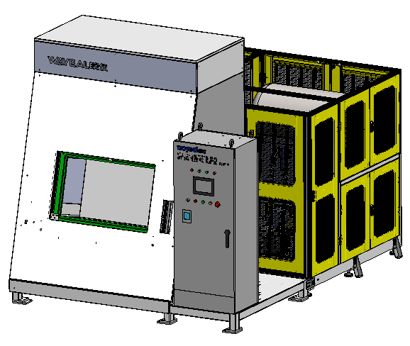
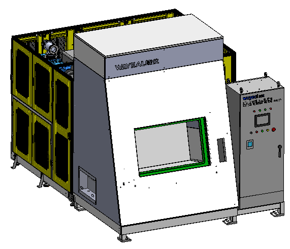
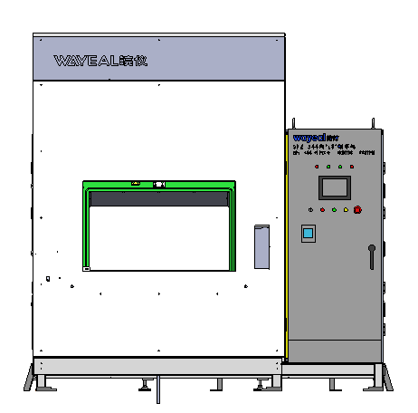
Nitrogen Gross Leak Pressure-Hold Detection

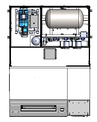
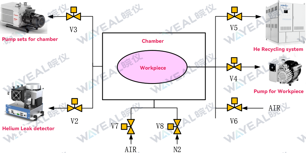
Place the workpiece into the vacuum chamber and complete the manual connection. Press the start button once, and the chamber door will close automatically. Valve V3 opens while all other valves remain closed. The vacuum chamber is pre-evacuated, and V1 opens to fill the workpiece with high-pressure nitrogen to the set pressure. The workpiece then enters a pressure-holding stage for several seconds.

If no gross leak is present, the pressure remains stable, and the system continues to the next testing stage.

If the pressure cannot be maintained within the preset time, the system determines that a gross leak exists in the workpiece and automatically triggers an audible and visual alarm. The system must then be stopped, the reset button pressed, and the workpiece removed after opening the chamber door.

2

Helium Micro Leak Detection

If no gross leak is detected, the system automatically opens V4 to evacuate the workpiece. At this stage, both the vacuum chamber and the workpiece are evacuated simultaneously.

When the chamber pressure reaches 30 Pa and the workpiece pressure reaches 2000 Pa, the helium leak detector starts automatically to measure and record the helium background level inside the chamber.

The measured leak rate during testing will be compensated by subtracting this background value, ensuring that the displayed value represents the actual leak rate of the workpiece.

After the background measurement is completed, V4 closes and V5 opens to charge the workpiece with low-pressure helium for micro leak testing.

The system automatically determines whether the workpiece passes the test and provides corresponding prompts or audible and visual alarms.

3

Helium Recovery

After completion of the micro leak test, the system automatically enters the helium recovery process.

Once recovery is completed, the system closes V1, V3, V4, and V5, and pauses the leak detector. Valves V6 and V7 then open to vent both the vacuum chamber and the workpiece. The workpiece can subsequently be removed, completing the test cycle.

III System Workflow

NG

OK

NG

OK

Manually place the liquid cooling manifold on the tray,
then manually connect the manifold and fixture piping

Manually push the fixture plate into the chamber,
then press the start button

The vacuum chamber door closes automatically,
and the chamber sealing mechanism automatically seals
the gas passage block on the fixture plate

Automatically evacuate the vacuum chamber,
while filling high-pressure gas into the manifold workpiece
to perform gross leak detection

Gross leak
check passed?

Alarm; automatically vent the manifold workpiece,
fill the chamber and open the chamber door

Remove leaking workpiece

After nitrogen discharge,
pre-evacuate the manifold workpiece to the set value

When the chamber reaches the set vacuum level,
the leak detection valve opens;
helium is filled into the manifold workpiece
for micro leak detection

Micro leak
check passed?

Alarm; automatically recover helium,
fill the chamber and open the chamber door

Remove leaking workpiece

Automatically recover helium,
fill the chamber and open the chamber door

Manually remove qualified workpiece

IV Main Optional Configurations

Components Brand Options
Helium Leak Detector Wayeal / Inficon / Leybold
Vacuum Pump Leybold / Edwards / Atlas Copco
Compressor Ingersoll Rand / Desran
Solenoid Valve GSR / COAX / CKD / SMC
Vacuum Gauge Wayeal / Inficon / Leybold
Pressure Sensor Micro Sensor / Airtac / WIKA
Vacuum Valve Wayeal / CKD
Safety Light Curtain Lion / SENSORC
PLC (Programmable Logic Controller) Schneider / Siemens / Mitsubishi / Omron / Inovance
Touch Screen Panel Weinview / Schneider Electric
Handheld Barcode Scanner Honeywell / Keyence
Industrial PC Advantech
Printer TSC
Electrical Components Schneider / Panasonic / IDEC, etc.

Configure SFZ-344 For Your Liquid Cooling Manifold

Send us your liquid cooling manifold dimensions, port layout, target leak rate, takt time, and automation needs. We will match the chamber, pump set, fixture, and helium recovery design to your process.